About Megacon
Worldwide contacts
Contact us
Megacon Home
Renewable Energy Solutions
Insulation Monitoring
AC Guards
AC Transducers
AC Trip Relays
AC High Voltage Adaptors
AC Loop Sensor Modules
DC Guards
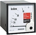
KPM169x
KCM169x
KPM169C2x
DC Trip Relays Live
DC Trip Relay Non-Live
DC High Voltage Adaptors
Insulation Test Unit
Earth Fault Monitoring
Earth Fault Protection
Battery Voltage Guard
Controllers and Guards
Current Guards AC or DC
Generator Protection
Generator Controls
Synchronisers
Freq. & Voltage Guards
Phase Sequence Control
Loss of Mains Protection
Measuring Transducers
Temperature Guards
Current Transformers
Panel Instruments
Switches
Shunts
Power & Test Equipment
Dewpoint & Hygrometers
Insulation Guards DC
KPM169x
BIPOLAR INSULATION GUARD FOR NON-GROUNDED DC NETWORKS
Direct connection 12 to 48 VDC systems, up to 1600VDC with RH adapter (up to 5000VDC on request)
(Panel mounting)
KCM169x
BIPOLAR INSULATION GUARD FOR NON-GROUNDED DC NETWORKS
Direct connection 12 to 48 VDC systems, up to 1600VDC with RH adapter (up to 5000VDC on request)
(DIN Rail mounting)
KPM169C2x
BIPOLAR INSULATION GUARD FOR NON-GROUNDED DC NETWORKS
Direct connection 12 to 48 VDC systems
(Panel mounting)
{1}
##LOC[OK]##
{1}
##LOC[OK]##
##LOC[Cancel]##
{1}
##LOC[OK]##
##LOC[Cancel]##
Web solution by Digitroll
 BIPOLAR INSULATION GUARD FOR NON-GROUNDED DC NETWORKS