KPM169C2x - BIPOLAR INSULATION GUARD FOR NON-GROUNDED DC NETWORKS
- Direct connection 12 to 48 VDC systems
- Precision reading unaffected of system voltage
- All inputs and outputs fully isolated
- Triple-zone insulation monitoring and Supervision relay
- “Pathfinder” Indicates polarity of dominant earth fault
- Response time: 125-165mS
- Analogue output proportional to meter reading (F-version)
Description
The digitally controlled KPM169C2x monitors insulation level between a live non-grounded (IT) battery or live DC network and its protective earth.
Only ONE KPM169C2x can be connected to the same DC-system. An AC or DC (standard) auxiliary voltage is required for the unit. A green LED indicates AUX POWER on. Start of monitoring function is delayed when auxiliary power is switched on (default 2 secs delay). In this way false tripping during power up, caused by initial charging of network spread capacitance, is avoided.
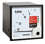
The DIN96 front-of-panel mounted instrument reads the insulation level directly in kΩ. The meter has reflection free glass. The ohmmeter and the triple-zone status LEDs at a glance gives the clear safety message:
General
SEV MEASURING PRINCIPLE
Insulation is measured between the complete galvanically interconnected DC network and its protective earth. The signal flows to ground via the path of the insulation fault, the level of flow expresses the insulation resistance, the direction of flow expresses the fault polarity. The measuring accuracy is not influenced by any normal kind of load attached to the network. The detection time for an insulation fault is 125-165mS.
PATHFINDER/POLARITY FUNCTION
During a Warning or Alarm condition the Polarity LED indicates the polarity causing the trip:
- POSITIVE EARTH FAULT: LED not lit
- NEGATIVE EARTH FAULT: blue LED lit
RELAY OUTPUTS
The unit has non-latching C/O relay outputs for Warning (R1), Alarm (R2)
and System Error (R3). The Alarm and error relays are fail to safety
configured. A trip LED flashes when the trip level is passed, the relay
trips after elapsed delay. The timer resets if the fault is removed
during countdown. Trip levels and delays are settable on unit rear.
Recommended trip level settings will depend on application and priority
of safety hazards.
ANALOGUE OUTPUT
All F and L versions have an isolated analogue output proportional to meter reading.
SYSTEM SUPERVISION
If voltage of the monitored DC system not connected to the unit
input or is to low, the NEG POLARITY LED will flash red, and relay 3
(System Error) will trip. If polarity of the input connection reversed,
the NEG POLARITY LED will flash red and blue, and relay 3 will trip.
Trip of relay 3 will inhibit operation of the warning and alarm relay
and their respective trip LEDs.
Description
KPM169C2x models for 9- 60VDC
Scale range: 0-30kΩ - ∞ (>33kΩ)
This unit is used for industrial, marine and offshore installations. Start of monitoring function is delayed when auxiliary power is switched on (default 2 secs delay). Direct connection for 12, 24 or 48VDC systems.
Models:
KPM169C2 & KPM169C2F
KPM169C2G & KPM169C2GF
KPM169C2H & KPM169C2FH
KPM169C2GH & KPM169C2GFH