The digitally controlled KSQ304EG2 is an automatic one-generator emergency or standby management system, which can be used with any make of GenSet starter together with Megacon's range of standard protective guards and controllers.
User settable limits on unit rear for frequency sync. difference, voltage differential, frequency reference, circuit breaker closing time, fuel regulator pulse width and pulse rate, load trim reference when parallelled to bus.
Note that the kW load signal input must be calibrated to 0-110% of generator nominal load.
Synchronising modes
To adapt the functionality of KSQ304EG2 to any specific application, the direction of approach to synchronising (LEAD, LAG or NEUTRAL) is factory set as required:
- LEAD (incomer faster than bus)
- LAG (incomer slower than bus)
- NEUTRAL (bi-directional)
LEAD is the standard mode. The synchronising relay will then close when the frequency of the incomer is slightly HIGHER than the bus frequency. This avoids a non-stabilised incomer entering reverse power condition after synchronisation.
The rotary LED display indicates the incomer's speed relative to the bus, and is lit during frequency mode if the difference between the systems does not exceeds 5Hz.
During all modes the UP/DOWN arrows indicate the pulses from the raise/lower speed relays.
Speed control
The raise/lower relays pulse the fuel regulator or an interfacing MXR845x electronic potentiometer. Pulse width and rate can be adjusted to suit the dynamic response of any fuel regulator. The speed control has a P/I (proportional/integral) characteristic with a dynamically controlled dead zone.
Alternatively the linear analogue -10/0/+10mA output signal can be used as speed reference to a generator controller, with polarity and amplitude proportional to frequency difference between the two systems when synchronising mode is selected.
System status:
KSQ304EG2 is fitted with a system status relay. As standard the unit is powered from generator side (terminal 3 & 4), when power is ok and unit is working correctly the relay activates. It will release on alarm or when unit is not powered. Separate auxiliary supply is needed for continuously system status.
Normal operation : Closed contact
Alarm condition/unpowered : Open contact
"SPOT ON" synchronisation - CB closing time compensation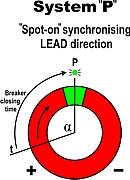
The dynamically controlled CB closing time compensation provides
SMOOTH synchronising, avoiding the engine/generator couplings being exposed to excessive torque forces. If
FAST synchronisation is the priority, accurate "SPOT-ON" synchronising will still be maintained even with a large frequency difference between the power sources. Typical setting for
smooth synchronising is 0,2Hz. The synchroniser operation and accuracy is not influenced by distorted voltage waveforms or harmonics.
Synchronisation
Green LEDs indicate voltage presence on supply source (BUS PWR only when generator is powered) and incoming generator (GEN PWR). Green LEDs also indicate that the voltage and frequency differentials between the two systems are within limits. The synchronising relay will close when the above conditions are achieved.
A green LED "CB CLOSE" indicates the closing command to the breaker. If any red LED is lit voltage and/or frequency is outside the set limits for synchronising.
Note: The CB Close LED will flash when unit is ready for
synchronising, but inhibit input is open or synchronising mode is not
selected.