KCQ106x2 - COMBINED "SPOT-ON" & SECTOR AUTOMATIC SYNCHRONISER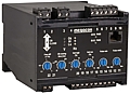
- The fast "Spot-on" synchroniser
- LEAD and/or LAG synchronising facility
- Sector Synchronising - with equal frequency
- Breaker closing time compensation
- Frequency differential analogue output
- Generator speed control (relays)
- Generator speed reference (analogue output)
- Systemstatus output
Description
The digitally controlled KCQ106x2 provides presentation of voltage
differential, relative speed and speed control output signals necessary
to achieve fast, automatic ”spot-on” synchronising between two systems.
If both of the frequencies are equal it uses sector synchronising with a
fixed values (See spcifications).
Its many important features contribute to make the KCQ106x2 simply the
best choice available for synchronising in any automatic generator
control system (PM-system).
KCQ106F2 is the standard and it takes the auxiliary voltage from the monitored voltage on terminal 3 & 4.
KCQ106G2 have separate auxiliary supply on terminal 19 & 20.
Applications
KCQ106x2 is used for both single and three phase systems. Any two phases
(or phase-neutral) can be used for synchronising as long as they are
the same two phases on both sides of the breaker. The synchroniser is
rated for continuous operation and can be left connected when not in
use.
Synchronising modes
To adapt the functionality of the KCQ106x2 to any specific application,
the direction of approach to synchronise an incomer (generator, busbar,
etc.) to the bus can be selected as required:
- LEAD (incomer faster than bus)
- LAG (incomer slower than bus)
- SECTOR (Change with equal Hz)
LEAD is generally the preferred mode. The synchronising relay will then
operate when the frequency of the incomer is slightly HIGHER than the
bus frequency. This is to avoid motoring of the incomer (entering a
reverse power condition) after the breaker is closed. If both LEAD and
LAG is connected it operate as nuetral (Bi-directional)
The up and down arrows indicate the incomer's speed relative to the bus.
Speed control
The raise/lower relays pulses the fuel control governor motor, or an
interfacing MXR845x electronic potentiometer. Pulse length and rate of
the speed control relays are adjusted on the rear of the unit to suit
the dynamic response of any engine regulator. The speed control has a
P/I (proportional/integral) characteristic, with a dynamically
controlled dead zone.
Alternatively the analogue -10/0/+10mA output signal can be used as
speed reference to a generator controller, with polarity and amplitude
proportional to frequency difference between the two systems.
System status:
KCQ106x2 is fitted with a system status relay. As standard the unit is
powered from generator side (terminal 3 & 4), when power is ok and
unit is working correctly the relay activates. It will release on alarm
or when unit is not powered. Separate auxiliary supply is needed for
continuously system status.
Normal operation : Closed contact
Alarm condition/unpowered : Open contact
"SPOT ON" synchronisation - CB closing time compensation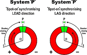
The dynamically controlled CB closing time compensation provides SMOOTH
synchronising, avoiding the engine/generator couplings being exposed to
excessive torque forces. If FAST synchronisation is the priority,
accurate "SPOT-ON" synchronising will still be maintained even with a
large frequency difference between the power sources.
The System "P" synchronising principle
The relay closure is initiated at "T" when the breaker coil is energised
and finalises at "P", assuring a precise "12 o'clock" synchronisation
(figs 1 and 2). Allowed frequency difference is adjustable between 0.1Hz
and 2Hz.
Typical setting for smooth synchronising is 0,2Hz. The angle "a" varies
according to the calculated frequency difference between the two
systems. The synchroniser operation and accuracy is not influenced by
distorted voltage waveforms or harmonics.
Synchronisation
Green lamps indicate voltage presence on reference source (BUS PWR) and
incoming generator (GEN PWR). Green lamps also indicate that the voltage
and frequency differentials between the two systems are within the
limits. The synchronising relay will close when the above conditions are
achieved.
A green lamp (CB close) indicates the close command to the breaker.
Frequency difference and voltage limits, circuit breaker closing time,
speed control relays pulse length/rate and synchronising mode are user
settable on the front of the unit.
Note: The CB Close LED will flash when unit is ready for
synchronising, but inhibit input is open or synchronising mode is not
selected.